
Transistor as an Amplifier Common Emitter Amplifier Circuit & Its Working
final amplifier transistors without mechani-cal headaches or oscillations. Figure 3 is the schematic of a 7 MHz version of the amplifier.1 It was optimized to use common, inexpensive ($0.79) switching power supply transistors. Since the 2N5739 is not designed as an RF device, there are no suggested RF operating conditions in In
transistor amplifier circuit diagram Electronics Help Care
7.2 INTRODUCTION. The single transistor amplifier is one of the major keys to understanding the. analysis and design of all analog electronic systems. Stereos, television sets, radios, long. distance telephone communication circuits, and many other practical systems employ. principles that we will explore in this experiment.
Simple Transistor Amplifier Circuit Diagram Wiring Digital and Schematic
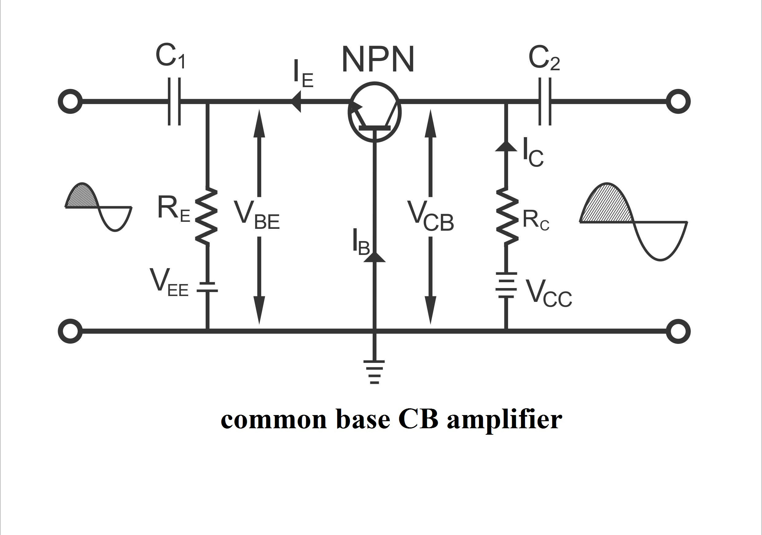
Basic Electronics Transistor as an Amplifier Working and Circuit Diagrams Engr Fahad April 26, 2022 2,619 Table of Contents BJT APPLICATIONS BJT Appliances Common Base (CB) Amplifier Circuit Operation of CB Amplifier Characteristics of a CB Amplifier Uses Common Emitter (CE) Amplifier Circuit Operation of CE Amplifier Current Gain Voltage Gain
Transistor Amplifiers Circuit Basics
Simple Transistor Amplifier Circuit Diagram . Working of Transistor as an Amplifier. In the above circuit diagram, we have made a voltage divider circuit using resistor R1 and R2 of 4.7k and 1.5k respectively. Hence, the output of the voltage divider circuit is used for proper biasing to turn ON the transistor. A transistor's base terminal.
Transistor as an Amplifier Circuit
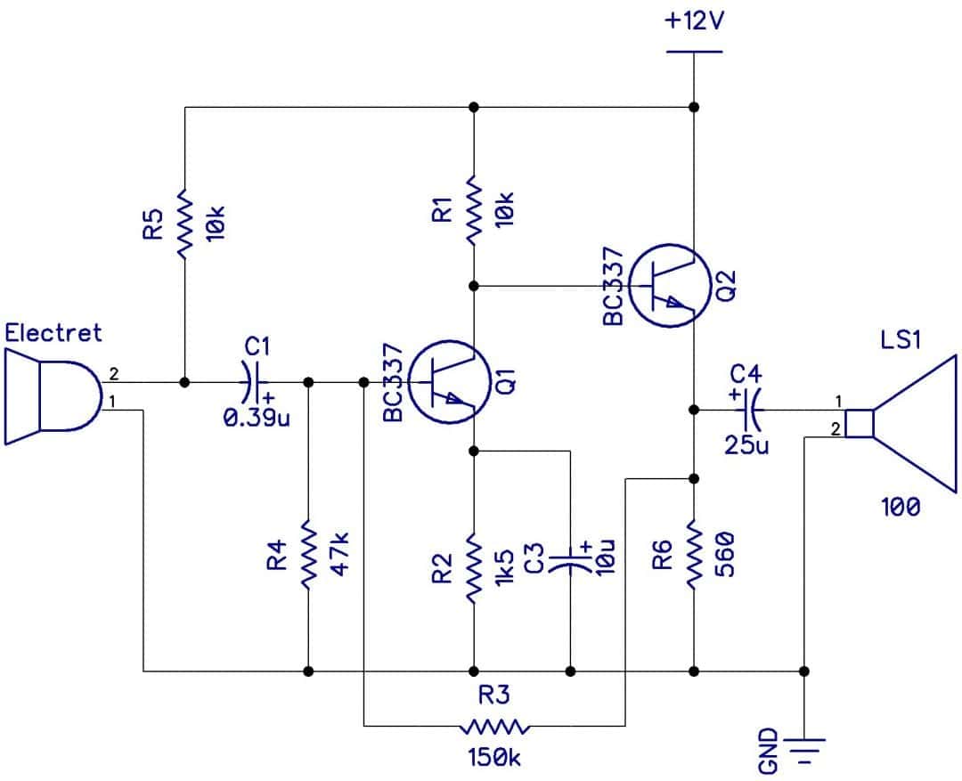
1. Intercom Circuit. 2. Audio Level Meter. 4. IR Headset. 5. How to Convert CD ROM to Audio CD Player. A simple transistor amplifier circuit diagram and schematic which can be used as a 12 watts audio transistor amplifier.An op amp IC is used to produce the gain required.
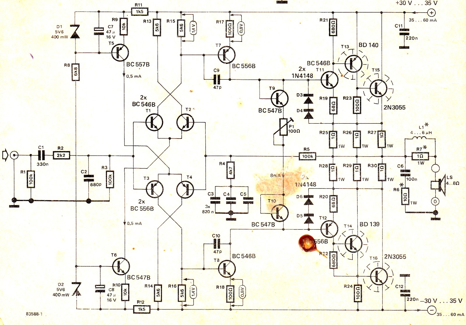
Transistor Power Amplifier Schematics
This electronics video tutorial provides a basic introduction into the Class A, AB, B, and C transistor amplifiers. The class A amplifier is the common emit.
How to Make a HiFi 100 Watt Amplifier Circuit Using 2N3055 Transistors
In electronics, amplifiers have been used since the early twentieth century. Amplification can be accomplished using vacuum tubes or semiconductor devices such as transistors or integrated circuits.. The amount of amplification in a circuit is known as gain.The gain is the ratio between the strength of the output (current, voltage, or wattage) and the strength of the input (current, voltage.
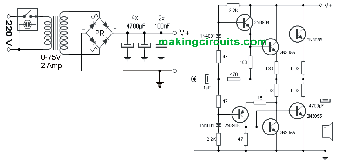
Simple 100 Watt Amplifier Circuit using 2N3055 Transistors
An amplifier circuit which is purely based on a transistor or transistors is called a transistor amplifier. Transistors amplifiers are commonly used in applications like RF (radio frequency), audio, OFC (optic fibre communication) etc. Anyway the most common application we see in our day to day life is the usage of transistor as an audio amplifier.
Darlington Transistor Amplifier Circuit Diagram IOT Wiring Diagram
The three basic transistor amplifiers circuit diagram: common-emitter transistor amplifier, common-base transistor amplifier, and common-collector transistor amplifier. Transistors are manufactured with two or three leads extending from their case. See Figure 4. These packages are accepted industry-wide regardless of manufacturer.
Transistor as an Amplifier Working and Circuit Diagrams Electronic Clinic
Transistor as an Amplifier - Circuit Diagram, and Its Working A transistor is a three terminal semiconductor device, and the terminals are E (Emitter), B (Base) & C (Collector). The transistor can work in three different regions like active region, cutoff region & saturation region.

Max Circuit Transistor As A Amplifier Circuit Diagram Pdf
Transistor Amplifier Circuits Unit 1 - Introduction to Transistor Amplifiers 2 NEW TERMS AND WORDS Multistage - an amplifier circuit that uses more than one active component (transistor). active component - a circuit component that controls gain or directs current flow. gain - the amount by which an amplifier increases signal voltage, current, or power; expressed as
Very simple amplifier circuit using transistor 2N3904
Circuit Diagram of Transistor Amplifier. Operation of Transistor Amplifier. During Positive half cycle of the input signal, the forward bias across emitter - base junction is increased. Hence, from the n - types emitter more electrons flow to the collector through the base. This increases the collector current.

2 Stage Amplifier Circuit using Transistors Electronics Infoline
Transistor amplifier's amplify an AC input signals that alternates between some positive value and a corresponding negative value. Then some way of "presetting" a common emitter amplifier circuit configuration is required so that the transistor can operate between these two maximum or peak values.
10 Watt Audio Amplifier Circuit Diagram using OpAmp and Power Transistors
The transistor amplifier circuit diagram typically includes the transistor itself, along with other passive components such as resistors, capacitors, and inductors. These components are arranged in a specific configuration to achieve the desired amplification of an input signal. The circuit diagram also shows the power supply connections.
Single Transistor Amplifier Circuit
The process of raising the amplitude of a weak signal without change in its frequency and shape is known as 'amplification". In order to achieve this, the input circuit of the transistor remains forward biased and the output circuit always remains to reverse biased during all parts of the signal this is known as 'transistor biasing'.
Simple Single Transistor Audio Amplifier Circuit
Take a look at these circuits. Maybe you get the idea of it. Table of Contents hide The Simple Audio Amplifier circuits without ICS 2N3904 transistor simple amplifier circuit 3 transistors power amplifier circuit Low Impedance Mini Amplifier Power Amplifier OTL using AC176+AC126 Power Amplifier OTL Cassette Radio Booster using TIP41+TIP42